Product Overview
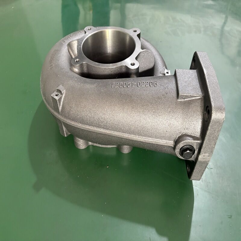
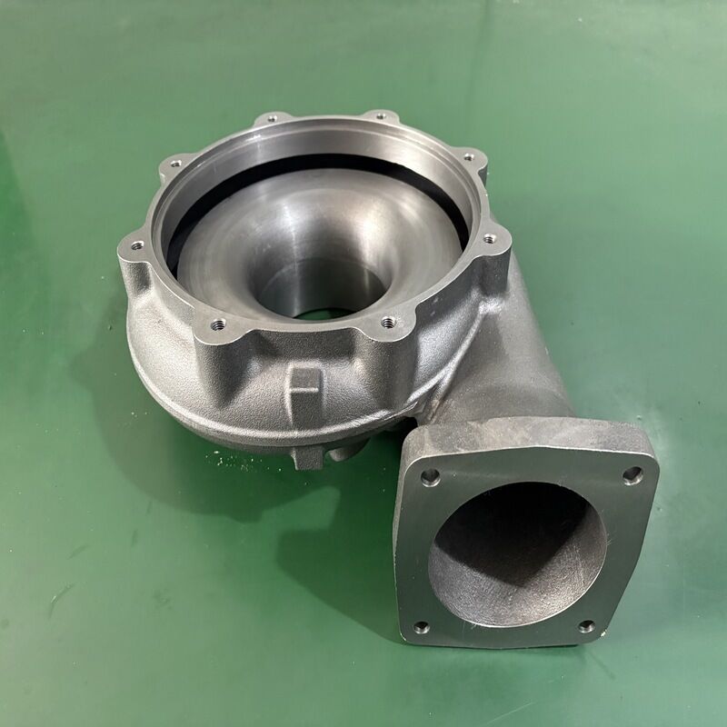
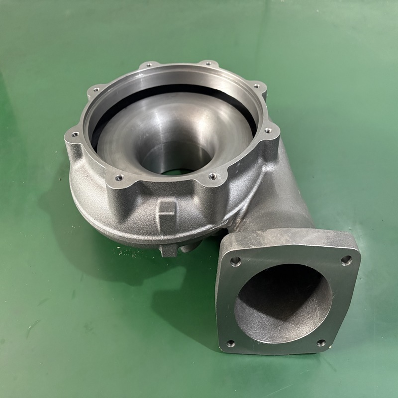
This heavy duty compressor casing is a core stationary component engineered for industrial centrifugal air compressors. Manufactured from high grade cast iron, it delivers exceptional structural integrity under continuous high pressure operation. The precisely shaped internal volute geometry efficiently collects and channels compressed gas, converting velocity into stable pressure while minimizing turbulence and energy loss. Every casing undergoes rigorous pressure testing and dimensional inspection to ensure a perfect fit with internal rotating assemblies. Designed for long service life in demanding environments, this compressor housing provides reliable performance in petrochemical processing, power generation, and large scale manufacturing. Its robust construction resists deformation and cracking, directly reducing unplanned downtime and maintenance costs.
Cause
Compressor operators frequently encounter critical problems caused by inferior or worn casings. Common issues include gas leakage at joint surfaces, casing erosion from corrosive process gases, and structural fatigue cracks that develop under cyclic loading. Low quality castings often contain hidden porosity or uneven wall thickness, leading to sudden pressure boundary failures. In high speed centrifugal compressors, a poorly designed volute profile creates excessive turbulence, which reduces aerodynamic efficiency and increases power consumption. These failures not only halt production but also pose serious safety risks to personnel and equipment. When a compressor casing cannot maintain tight clearances and stable sealing, the entire compression system suffers from rising vibration, lower discharge pressure, and escalating energy bills.
Solution
Our heavy duty cast iron compressor casing directly addresses these operational failures at the root. We utilize precision casting techniques with strict metallurgical control to produce a dense, defect free structure capable of withstanding design pressures far beyond standard ratings. The internal flow path is CNC machined to exact volute profiles, ensuring smooth gas collection from the impeller and optimal pressure recovery. Each unit is hydrostatically tested at 1.5 times the maximum working pressure and inspected with ultrasonic methods to guarantee zero leakage and structural soundness. By replacing a degraded casing with our solution, you restore correct impeller tip clearance, eliminate efficiency robbing turbulence, and secure stable long term compression. The result is measurable reduction in energy consumption, extended service intervals, and a safer operating environment.
Specifications
| Parameter |
Value / Range |
| Material |
High grade gray cast iron (e.g. HT250, GG25) or ductile iron |
| Max Working Pressure |
Up to 25 bar (custom higher pressure options available) |
| Temperature Range |
-20°C to 350°C (depending on material) |
| Inlet/Outlet Size |
Custom from DN100 to DN800 |
| Applicable Compressor Type |
Single stage and multi stage centrifugal compressors |
| Machining Accuracy |
Tolerance within 0.02 mm on critical sealing surfaces |
| Testing Standard |
Hydrostatic test per ASME or customer specification, ultrasonic inspection |
| Surface Treatment |
Anti rust primer, epoxy coating, or customer specified painting |
| Connection Type |
Flanged (ANSI, DIN, JIS, GB) or machined for direct coupling |
Custom materials such as cast steel or stainless steel are available for corrosive gas applications.
Application
Oil and gas processing and gas gathering stations
Petrochemical and chemical plants (process air, hydrogen recycle, synthesis gas)
Power generation turbine auxiliary systems
Large scale industrial air separation units
Steel mill and mining compressed air systems
Wastewater treatment aeration blowers
Pharmaceutical and food grade compressed air systems (with appropriate coatings)
How It Works
A compressor casing forms the stationary pressure boundary and aerodynamic flow passage of a centrifugal compressor. As the impeller rotates at high speed, it throws gas outward by centrifugal force. The casing volute spiral shaped channel receives this high velocity gas and gradually expands in cross sectional area. This expansion decelerates the gas, converting kinetic energy into static pressure according to Bernoulli’s principle. Simultaneously, the casing contains the pressure and directs it toward the discharge nozzle. In multi stage compressors, intermediate casings equipped with diffuser passages and return channels guide the gas to the next impeller. The rigid casing structure also maintains precise alignment of bearings and seals, keeping rotor vibration within safe limits and preventing internal rubs.
How To Choose
Confirm Compressor Model and Dimension – Provide your existing casing drawing or the compressor model number. We need the inlet and outlet diameters, mounting bolt pattern, and overall envelope dimensions.
Define Operating Pressure and Temperature – Specify the maximum continuous working pressure and gas temperature. This determines the required material grade and wall thickness.
Identify Gas Composition – If the gas contains moisture, hydrogen sulfide, or other corrosive components, advise whether upgraded materials such as cast steel or stainless steel are needed.
Check Connection Standards – Confirm flange standards (ANSI B16.5, EN 1092, etc.) and facing type to ensure a leak free fit with your existing piping.
Assess Operating Speed and Rotor Details – Knowing the impeller diameter and rated speed helps us verify the volute throat area and ensure aerodynamic matching.
Share Site Environment – For outdoor or offshore installations, additional corrosion protection or special coatings may be recommended.
FAQ
1. Can you manufacture a compressor casing based on a sample or existing drawing?
Yes. We accept reverse engineering from a used casing or your own 2D/3D drawings. Simply send us the physical part or a detailed dimensional sketch, and we will reproduce it with full material certification.
2. What materials are available aside from cast iron?
Besides high grade cast iron, we can supply casings in cast steel, low temperature carbon steel, and 304/316 stainless steel for corrosive or high temperature applications. Please tell us your process gas composition for a material recommendation.
3. How do you ensure the casing does not leak under high pressure?
Every casing undergoes a hydrostatic pressure test at 1.5 times the design pressure. We also perform ultrasonic wall thickness checks and dye penetrant inspection on critical areas. A certified test report is supplied with each unit.
4. What is the typical delivery time for a custom compressor casing?
Standard delivery ranges from 30 to 50 days, depending on the size and complexity. For urgent breakdown replacements, we offer expedited production in as little as 20 days. Contact us with your requirements for a precise schedule.
5. Do you provide installation support or technical guidance?
We provide a detailed installation manual and can offer remote technical assistance during commissioning. On site supervision by our engineers can also be arranged for large or complex projects.

 پیام شما باید بین 20 تا 3000 کاراکتر باشد!